
Field Recording Equipment Troubleshooting: Diagnosing Common Problems
Field recording equipment troubleshooting works best when you start with the observable symptom and change one variable at a time. Verify the recorder state first, then trace the relevant path—file writing, source-to-input signal, gain and headroom, noise trigger, or power—and treat a component as faulty only when the symptom reliably follows it under a controlled comparison.
Use the recorder's record state, input meters, resulting file, monitoring output and power behaviour as checkpoints. A result at one checkpoint tells you which part of the recording chain to inspect next; it does not automatically prove a specific component has failed.
Table of Contents
Recorder Will Not Start or Complete a Recording
A field recorder that will not record should first be classified by what happens: the take never starts, it starts but stops early, or the recorder appears to run but produces no usable file.
Check the visible recording state and record indicator before changing other settings.
An error shown when recording starts or stops can further narrow the condition, but indicator behaviour and controls can differ by model.
The first diagnostic branch is therefore the recorder state followed by the file-write condition on the media.
| Observed symptom | Likely condition | First check | Next action |
|---|---|---|---|
| The take never starts | The field recorder may not have entered its recording state, or a hold or lock state may be preventing the expected control action. | Verify the recording state, record indicator, visible hold or lock status, and any displayed error. | Use the model-specific control indication to confirm that record mode is active before testing file writing. |
| The take starts but stops early | The recording state may have ended because the recorder could not continue writing the file. | Check for a visible error and verify whether the media remains available for writing. | If the recorder indicates a write-related condition, inspect the media state and file-write availability before repeating the take. |
| The recorder appears to run but no usable file is produced | The recorder may have entered its recording state without completing the expected file on the selected media. | Confirm the final recording state, inspect visible errors, and check whether the expected file exists on the selected media. | If the recording state is confirmed but the expected file is absent, continue with the file-write condition rather than the record control. |
The diagnostic split is whether the field recorder enters record mode and whether that state produces the expected file on the selected media.
If the expected record indicator does not appear, check the recording state, controls, and any visible hold condition first; if the recording indication appears but no usable file results, check the file-write condition instead.
A take that stops early also shifts attention to any displayed error and whether writing can continue, without proving a storage or hardware fault.
The image below shows this distinction between the recorder's visible operating state and the resulting file.
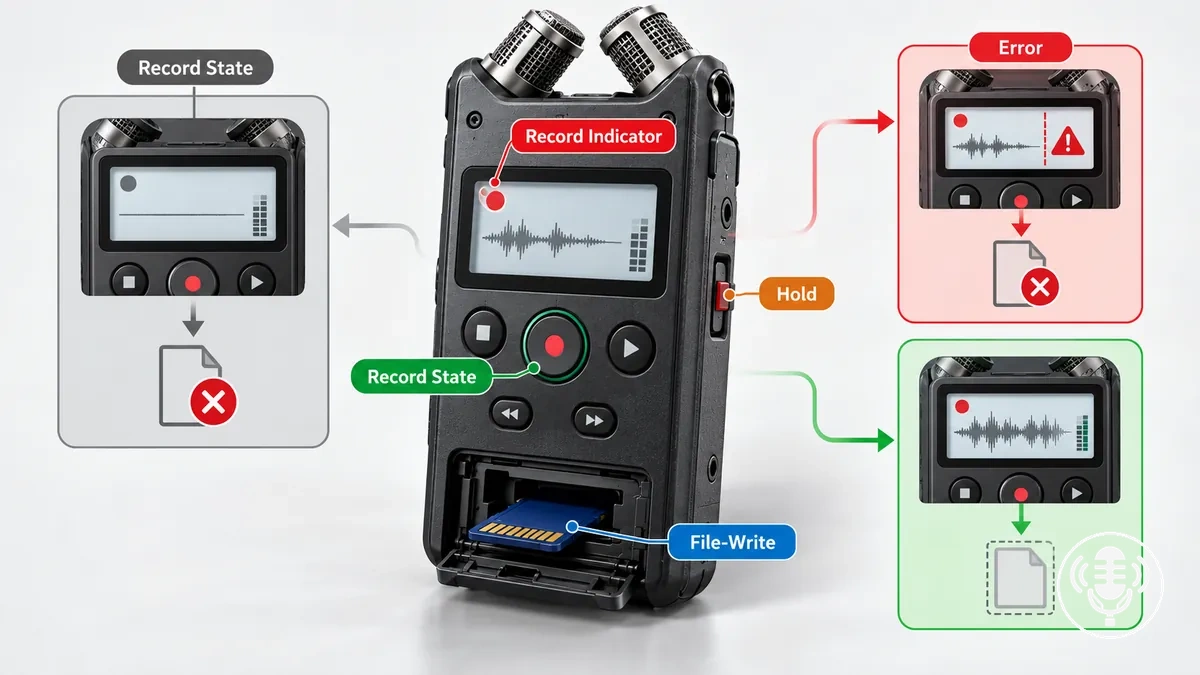
For example, if pressing record produces no record indicator while hold is active, verify the control state before investigating file writing.
If the model-specific recording indication appears but the expected file is absent after the take ends, verify the media and file-write condition instead.
This separates a control-state failure from a file-write failure without moving into battery or input-signal diagnosis.
Record Mode, Hold State and File-Write Conditions
A field recorder can power on normally yet fail to start or complete a take when record mode is inactive, a hold state or lock state blocks the controls, or the media is not ready to write a file.
The recording indicator provides the first visible check of whether the recorder has entered its expected recording state.
Verify record mode first, then the hold or lock state, and then file writing.
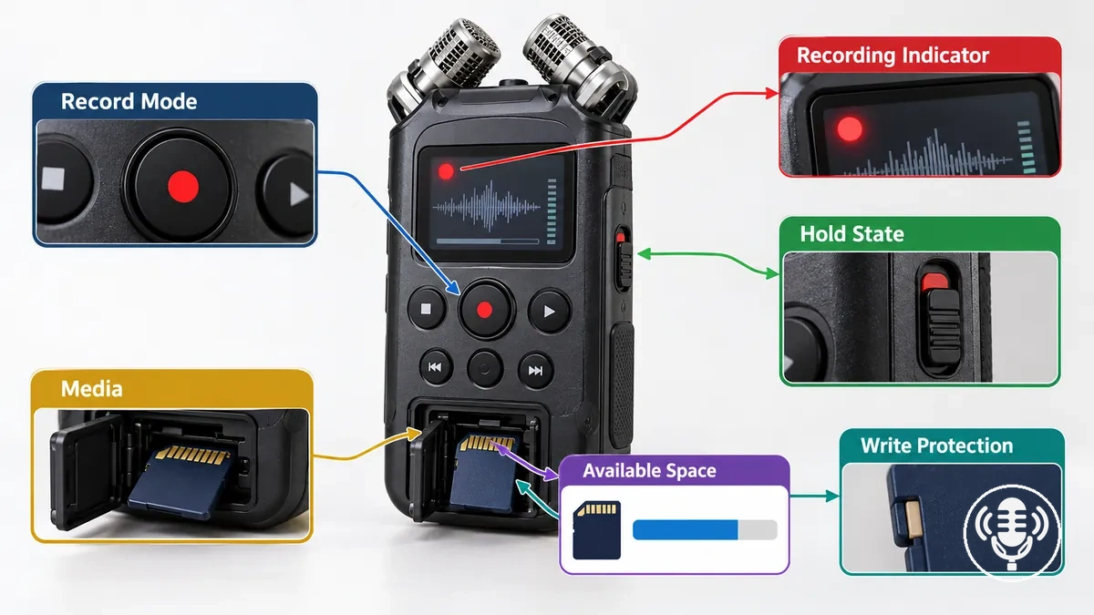
- Record mode: Verify that the recorder is in its recording state and shows the expected recording indicator for that model; if the expected indication is absent, confirm the recorder state before checking file writing.
- Recording indication: Check that the recording indicator changes to the model-specific active-recording indication; if it does not, verify the control state rather than assuming a file-write problem.
- Media compatibility: use a media type and preparation method supported by the recorder. Compatibility, recognition, available space and writable state are separate conditions.
- Media recognition: Confirm that the recorder recognises the selected media; if it does not, verify the media state before checking available space.
- Available space: Confirm that the recognised media reports enough available space for a new file; if it does not, free space or select suitable media before another recording attempt.
- Write protection: Check whether write protection is active on media that provides that state; if writing is blocked, set the media to a writable state before another recording attempt.
If recording does not begin, work through the checks in order so the observed state determines the next check rather than an assumed cause.
A normal recording indicator shifts attention from the control state toward media recognition, available space, and write protection, while an absent indication keeps the check on record mode and the hold or lock state.
The image below shows these local state relationships and the sequence from recorder controls to file-write readiness.
Recorder Records but Has No Input Signal
A field recorder that creates recording files but shows no input signal should be traced from the source output to the meter response before recorder failure is assumed.
Start by confirming that the source produces the expected signal, then follow that signal through each connection and recorder stage.
A missing meter response means the input signal has not yet been verified at the recorder's metering stage.
Trace the signal path in this order
- Source output: confirm that the microphone or other source produces a signal in its normal operating condition.
- Cable and connector: verify that the connection carries that signal to the intended recorder input.
- Input and channel: match the input type to the source and enable the channel receiving that connection.
- Microphone power, when required: use only the power method supported by both the microphone and the recorder input.
- Meter response: activate the source and watch the selected input meter. Movement verifies that signal has reached the metering stage; no movement keeps the diagnosis upstream of that point.
The image below shows the same source-to-meter sequence and the points where signal presence should be verified.
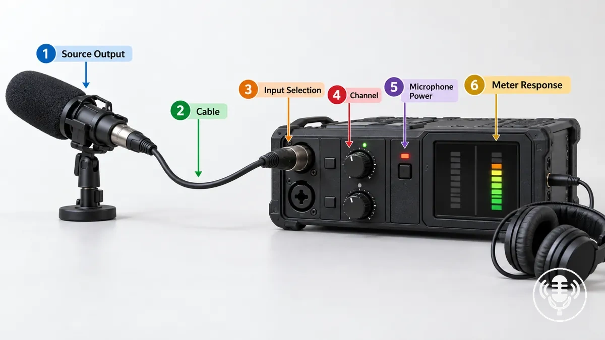
If the meter responds to the source but no sound is heard through the monitoring output, the input signal is present at the metering stage and the next check belongs to the monitoring path.
If the meter remains inactive, continue verifying the source output, cable, input selection, channel state, and any applicable microphone power condition.
This distinguishes absent input activity from a monitoring-only problem.
Input Source, Channel Selection and Microphone Power
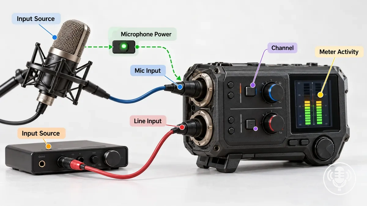
An input signal appears only when the input source, channel selection, and required microphone power match the connected source.
Where the field recorder provides both options, select a mic input for a microphone-level source or a line input for a line-level source, and make sure the intended channel is enabled.
Microphone power is a separate condition and should match the connected microphone's power requirement.
Check source selection, channel state, and microphone power separately before interpreting meter activity.
- Mic or line selection: Where the recorder provides mic input and line input modes, match the selected input to the connected source type; if they do not match, verify the input source before using meter activity to judge the signal.
- Channel enablement: Verify that the channel receiving the connected source is enabled; the expected result is meter activity on that selected channel when a signal reaches it.
- Microphone power: If the source requires recorder-supplied power, use the exact power method supported by both the microphone and that input. Phantom power and plug-in power are different systems and are not interchangeable; a self-powered source should be checked according to its own requirement.
- Meter activity: Activate the source and observe the input meter; activity indicates that a signal has reached the selected input and channel, while no activity means the local source selection, channel state, and applicable power requirement still need verification.
Work through these checks as setting-to-signal relationships rather than assuming one recorder configuration applies to every source.
The selected input must match the source type, the intended channel must be active, and any microphone power must match the connected microphone's requirement before the expected meter activity can be assessed.
The image below shows these local configuration checks and their relationship to the input meter.
If a correctly connected source remains silent, verify these local input conditions before changing unrelated recording settings.
If the input source, channel selection, and required microphone power match but meter activity remains absent, continue diagnosis outside this local configuration check rather than treating it as a general setup problem.
Cables, Connectors and Source Output
A silent recorder input can originate before the recorder when the source output produces no signal or the connector and audio cable path do not pass the expected signal to the recorder input.
A connector that is not fully seated can interrupt the connection, while one silent take alone is insufficient to identify the cable or connector as faulty.
Verify the physical signal path
- Confirm source activity: establish that the connected source is producing the expected signal.
- Reseat both ends: make sure each connector is fully seated, then check whether the recorder meter changes.
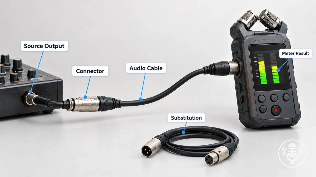
- Substitute one cable: if the symptom remains, replace only the suspected cable with a compatible known-good cable and compare the meter result.
- Test where appropriate: a continuity or cable test can support a cable diagnosis, but adapters and balanced/unbalanced wiring matter only when they alter the signal path being tested.
The image below shows the physical connection from source output through the connector and audio cable to the recorder input, with the meter result as the observable check.
Recording Level Is Too Low, Clipped or Distorted
A recording level that is too low, clipped, or audibly distorted can originate at different signal stages, so recorder level alone does not identify the cause.
A weak source output or low microphone or capsule output can deliver too little signal to the preamp or input stage, while excessive level can overload an upstream stage or exceed recorder headroom.
Meter behaviour helps locate the condition but represents only the stage being measured.
No universal recorder-level target identifies all three conditions because the useful indication depends on which signal stage the meter represents.
Isolate the responsible signal stage before changing gain or sensitivity.
For a low recording level, first determine whether the incoming signal is already weak or whether gain or sensitivity at the recorder is too low for that source.
Increasing gain can raise the recorder's measured level, but it does not correct a source output or microphone stage that is failing to produce the expected signal.
For clipping, determine whether the recorder meter indicates that its measured stage has reached its available headroom or whether audible distortion is already present before that point.
These distinctions determine the first check in the diagnostic table.
| Symptom | Likely signal stage | Useful meter clue | First check |
|---|---|---|---|
| Recording level remains too low | Source output, microphone or capsule, or recorder gain or sensitivity | Meter activity remains low while the source is active | Verify that the source and microphone or capsule produce the expected output, then check gain or sensitivity for that input. |
| Recorder-stage clipping | Preamp, input stage, or recorder stage at its available headroom limit | The measured level reaches the recorder's clipping or overload indication | Reduce the level feeding the overloaded stage or reduce gain or sensitivity at that stage, as applicable. |
| Audible distortion without a recorder clipping indication | Source output, microphone or capsule, or another upstream stage | The recorder meter remains below its clipping indication while audible distortion is present | Check the upstream source, microphone or capsule, and preamp or input stage for overload before changing recorder gain solely from the meter reading. |
A clean recorder meter does not prove that the whole recording chain is clean.
A source output, microphone or capsule, or upstream preamp can overload before the signal reaches the stage represented by the recorder meter, so audible distortion can remain without recorder-stage clipping.
Conversely, a recorder clipping indication identifies excessive level at the stage being metered rather than proving that the source itself is distorted.
The isolating clue is whether distortion exists upstream of the measured stage or appears when the recorder reaches its available headroom.
Recording-level diagnosis should identify the stage responsible for low level, clipping, or distortion rather than serve as a general judgement of recording quality.
Broader audio quality and noise performance depend on characteristics outside this stage-level diagnostic check.
Low Signal from Source Output, Input Sensitivity or Gain
A low recording level should be traced from the source output through input sensitivity, gain, and any applicable attenuation before a field recorder hardware fault is suspected.
If the source output is low, the recorder receives less signal; if the selected input mode or sensitivity reduces the effective incoming level, the meter level can remain low even when the source is active.
Gain can raise the level at the recorder stage, while attenuation or a pad, when active, reduces the signal level reaching the following stage.
Low-level check sequence
- Source output: verify that the source and microphone or capsule are producing the expected signal.
- Input mode or sensitivity: match the recorder input to the connected source type before judging meter level.
- Attenuation or pad: if one is active, remember that it deliberately reduces the level reaching the following stage; disable it only when the source condition does not require it.
- Gain: increase gain only after the earlier stages are verified, watching the meter so the recorder level rises without driving the measured stage into overload.
The useful gain setting depends on source output and recorder configuration; there is no single meter target that is correct for every field recording.
A low signal that remains after these checks requires further diagnosis, but low level alone does not prove a hardware fault.
Recorder Clipping Versus Microphone or Preamp Overload
Recorder clipping occurs when the signal overloads the recorder stage being measured, while microphone overload or preamp overload occurs earlier in the signal path.
The recorder meter can indicate the digital level at its measured signal stage, but it does not establish the headroom available at an upstream microphone, capsule, or preamp stage.
At a digital metering stage, 0 dBFS is the digital ceiling: reaching it leaves no additional digital headroom at that stage. An analogue microphone, capsule or preamp can still overload earlier, so a meter reading below 0 dBFS does not guarantee that upstream stages are clean.
A loud source can therefore produce microphone overload or preamp overload and audible distortion while the recorder meter remains below its digital clipping indication.
Distortion can occur before the recorder reaches its digital clipping point.
| Overload location | Overload condition | Meter evidence | Audible outcome and isolating check |
|---|---|---|---|
| Recorder stage | The signal reaches or exceeds the available headroom at the recorder stage being measured. | The recorder meter indicates clipping or overload at that measured stage. | Distortion can result at the recorder stage; reduce the level feeding that stage and check whether the clipping indication and distortion change. |
| Microphone or capsule stage | The microphone or capsule overloads before the signal reaches the recorder's measured stage. | The recorder meter can remain below its clipping indication because the overload occurred upstream. | Distortion can already be present; reduce the level presented to the microphone or capsule where practical and check whether the distortion changes. |
| Preamp stage | The preamp overloads when its input signal exceeds the headroom available at that signal stage. | A downstream recorder meter can remain below its clipping indication because it does not establish the preamp's upstream headroom. | Distortion can occur before recorder clipping; reduce the level entering the suspected preamp stage and check whether the distortion changes. |
If a recording sounds distorted while the recorder meter does not show digital clipping, check for microphone overload or preamp overload before treating recorder clipping as the cause.
Meter evidence should be interpreted for the signal stage it represents, because a sub-clipping recorder reading does not establish that upstream stages remain within their headroom.
If reducing the level entering a suspected upstream stage changes the distortion while the recorder meter remains below its clipping indication, that result supports an upstream overload diagnosis.
Use the isolating check that changes the level entering the suspected signal stage rather than applying a universal fix.
Unexpected Noise Appears in Field Recordings
Unexpected noise in field recordings should first be narrowed by when it appears and what changes it before a corrective action is chosen.
Similar-sounding noise can come from different source classes, so sound character alone is not enough to assign a cause.
A repeatable trigger and the conditions that change the noise are more useful diagnostic evidence than description alone.
Find the trigger before choosing the fix
- Reproduce: repeat the same recording condition and note whether the noise is continuous, intermittent or tied to a repeatable event.
- Test movement: move the recorder, microphone, cable or support one item at a time. A repeatable response points toward a mechanical trigger.
- Test the environment: keep the equipment still while changing wind exposure, position or another external condition. A repeatable response points toward an environmental trigger.
- Test routing and power: if the first two branches do not explain it, change one cable-routing, power or RF-proximity condition at a time. A repeatable response supports an electrical-interference branch.
A repeatable change identifies a source class; it does not by itself prove the exact source of the noise.
Detailed classification of environmental, mechanical, and electrical noise belongs to the next diagnostic step.
Wind-related noise should be assigned to an environmental source only when changes in wind exposure or microphone position produce a repeatable change in the symptom.
Detailed wind noise control is a separate mitigation task after the source has been isolated.
Identify Whether Noise Is Environmental, Mechanical or Electrical
Classify unwanted noise by its trigger and repeatability rather than by sound character alone.
A noise that changes consistently with a specific condition provides a stronger classification clue than a hiss, bump, buzz, or other sound description by itself.
Repeat the suspected condition and observe whether the symptom changes with it.
The three local source classes are environmental noise, mechanical noise, and electrical interference.
If the source class is unclear, change one suspected condition at a time and check whether the noise responds.
Environmental noise can correlate with wind, location, or another external condition; mechanical noise can respond to handling noise, cable movement, or recorder movement; electrical interference can change with cable routing, power conditions, or proximity to an RF source.
A repeatable response supports that source class but does not establish an exact cause without further isolation.
The table compares the trigger, isolation test, and next diagnostic action for each class.
| Noise class | Typical trigger | Simple isolation test | Likely next action |
|---|---|---|---|
| Environmental noise | Wind, location, or another external environmental change coincides with the symptom. | Keep the equipment configuration stable while changing the suspected environmental exposure and check whether the noise changes repeatably. | Continue isolating the environmental condition that changes the symptom before choosing a specific control method. |
| Mechanical noise | Handling noise, cable movement, recorder movement, or movement of a support coincides with the symptom. | Move the suspected component separately while other conditions remain stable and check whether the noise repeats with that movement. | Identify the component or movement that reproduces the symptom before applying a mechanical-noise remedy. |
| Electrical interference | The symptom changes with cable routing, power conditions, or proximity to a potential RF source. | Change one routing, power, or RF-proximity condition at a time and check whether the hum, RF-related symptom, or other unwanted noise changes repeatably. | Continue isolating the electrical condition associated with the change before selecting an interference-control action. |
If wind exposure changes the noise while the equipment remains otherwise stable, environmental noise becomes the stronger classification; if moving a cable or recorder reproduces the symptom, mechanical noise becomes the stronger classification.
If hum, RF-related noise, or another symptom changes when cable routing, power, or RF proximity changes, electrical interference becomes the stronger classification.
These observations support a source class rather than proving an exact cause from sound character alone.
Handling noise problems require separate mechanical diagnosis after movement is isolated as the trigger.
RF, hum, and electrical interference require separate electrical isolation after a routing, power, or RF condition is shown to change the symptom.
Recorder Shuts Down or Drains Batteries Unexpectedly
An unexpected shutdown or rapid battery drain in a field recorder should be separated into battery condition, contact problems, unusual recorder power demand, and unstable external power before recorder failure is assumed.
Check whether the battery has an adequate charge for the recorder's current configuration, then whether the battery and contacts remain securely connected.
If the symptom appears only under a particular operating condition, treat that condition as a possible change in power demand rather than assuming a fixed battery runtime.
One shutdown is not enough to identify a recorder fault.
Keep battery condition, contact integrity, recorder load, and external power stability as separate diagnostic branches.
Separate the power path
Internal battery
- Verify charge state and battery condition.
- Confirm secure seating and consistent contact.
- When safe and compatible, compare with a suitable charged battery.
- Interpret runtime together with battery type, battery condition and the recorder's operating load.
External power
- Confirm that the connection remains secure when the symptom occurs.
- Verify that the source continues supplying the recorder under its actual operating condition.
- If moving the connection reproduces the shutdown while internal power is stable, isolate the external cable, connector or supply path first.
- Use only a power arrangement that matches the recorder's specified electrical and connector requirements.
Battery Condition, Contacts and External Power Stability
Check battery state, battery seating, contacts, and charge state before treating a shutdown as a recorder problem.
The battery should show no visible damage, sit securely in its intended position, and maintain contact while the field recorder operates.
A charge indication alone does not establish that every part of the power path remains stable.
Verify battery condition first, followed by battery seating, contacts, and charge state.
For external power, compatibility includes the recorder's required electrical specification and connector arrangement; a source showing charge is not sufficient if it cannot maintain the recorder's required input under load.
- Battery state: Check for visible damage or leakage; if either is present, stop using that battery rather than continuing the power test.
- Battery seating: Confirm that the battery is seated in its intended position; if recorder behaviour changes when the battery loses its connection, investigate the seating before assuming an internal recorder fault.
- Contacts: Check that the battery contacts are unobstructed and maintain contact during normal operation; an intermittent connection keeps the diagnosis within the battery power path.
- Charge state: Verify that the power source reports an adequate charge for the intended test; one shutdown or charge indication alone is insufficient to label the battery faulty.
- External power: If an external power source is used, verify that its connection remains secure and that it continues supplying the recorder when the symptom occurs.
If external power is suspected, observe whether the power supply remains stable when the recorder behaviour changes.
A shutdown that repeats when an external-power connection is interrupted supports an unstable external path, while stable operation after that connection is restored shifts the next check toward the external supply or connection rather than the battery contacts.
If a power bank or other external power source shows charge but the recorder still loses power, verify whether the source continues to supply power under the recorder's operating condition.
A charged source can still produce unstable recorder behaviour under some conditions, so the observed interruption should be isolated before a fixed cause is assigned.
When a Cable, Microphone or Recorder Component May Be Faulty
A component fault becomes more plausible when configuration, power and connection variables are controlled but the same repeatable symptom remains.
Treat the cable, microphone, connector or recorder input as the suspected component only when its behaviour can be reproduced under otherwise working conditions.
Physical damage or intermittent behaviour can strengthen that suspicion, but neither proves which component has failed.
Fault confidence should rise only when the symptom consistently follows one component.
When suspicion becomes stronger
Cable or connector
The signal fails with the suspected cable, passes when only that cable is replaced with a compatible known-good cable, and the result repeats.
Microphone
The same microphone reproduces the symptom through another otherwise working, compatible signal path while the comparison microphone does not.
Recorder input
The same known-good microphone and cable work through another equivalently configured input but repeatedly fail on the suspected input.
These controlled comparisons support a component diagnosis; they are not automatic proof of the underlying failure mechanism.
If a suspected component repeatedly fails a known-good comparison and also shows physical damage or repeatable intermittent behaviour, professional service or replacement becomes more reasonable to consider.
Visible connector damage is a stronger service cue when it occurs with the same reproducible signal problem.
Do not base that decision on a single failed recording or an isolated interruption.
When substitution results are inconsistent or the symptom does not reliably follow one component, keep the diagnosis uncertain and continue external testing rather than assuming a component fault.
Confirm the Faulty Component by Substitution or Cable Testing
Fault isolation is strongest when one variable is changed at a time and the suspected component is compared with a known-good substitute or an appropriate cable test.
The useful result is whether the symptom reproduces, disappears, or persists while the rest of the signal path remains unchanged.
Use one-variable-at-a-time substitution so the observed result can be tied to the component being tested.
- Confirm the symptom: Reproduce the same symptom before changing a component so there is a consistent starting condition for comparison.
- Substitute one component: Exchange only the suspected component for a known-good substitute while keeping the remaining signal path unchanged. If the symptom disappears with the substitute and reproduces when the suspected component is restored, that repeatable result strengthens the fault diagnosis.
- Run a cable test where appropriate: For a suspected cable, disconnect it from the recording equipment and use an appropriate cable test or continuity check. A repeatable connection failure supports suspicion of the cable, while a passing result returns attention to other parts of the signal path.
- Compare the results: Determine whether the symptom follows the suspected component, disappears with the known-good substitute, or persists with both. A symptom that repeatedly follows one component provides stronger fault-isolation evidence than an inconsistent result.
- Make the decision: Consider repair or replacement when controlled tests repeatedly point to the same component. If the results are inconsistent, keep the component diagnosis open rather than treating the fault as confirmed.
If the checks produce a repeatable result that follows the suspected component, that component becomes the stronger repair-or-replacement candidate, although uncontrolled variables can still limit certainty.
If the symptom does not follow the substituted component, return the diagnosis to the remaining signal path rather than forcing a replacement conclusion.