
Field Recording Equipment Connection Compatibility: Inputs, Outputs and Channels
To verify field recording equipment compatibility, match the complete signal path: source and input direction, mic- or line-level handling, any required microphone power, connector wiring, usable channels and record tracks, and the output role at the destination. A connector that physically fits is not sufficient; every required signal, power, wiring, routing, and destination condition must match the specific configuration.
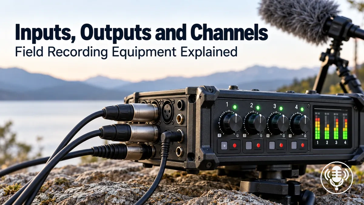
Connection compatibility decision map
Check these layers in order. Each layer answers a different compatibility question, so one successful check cannot substitute for another.
- Direction and roleSend a source into an input; send a recorder output to the intended destination. Do not treat an input, output, channel, or track as the same thing.
- Signal levelMatch microphone-level sources to suitable mic-input handling and line-level sources to suitable line-input handling. Gain and sensitivity remain recorder-specific.
- Microphone powerUse phantom power, plug-in power, self-power, or no recorder-supplied power only when that is the connected microphone's specified requirement.
- Connector and wiringConfirm connector size and gender, pin/contact assignment, balanced or unbalanced implementation, and channel arrangement. XLR, TRS, or 3.5 mm appearance alone does not define these properties.
- Capacity and routingMake sure the required sources can enter, use available signal paths, and reach the required record tracks simultaneously in the selected recorder mode.
- Output destinationMatch headphone outputs to headphone monitoring and line outputs to compatible destination inputs, then verify level control and routing for that output.
Decision rule: if any required layer is unknown or mismatched, treat the connection as unverified even when the plugs mate physically.
Use the sections below to check each layer separately. Where gain range, phantom-power setting, routing, or output behaviour is model-specific, use the recorder and connected-device specifications rather than inferring capability from connector shape.
Table of Contents
Inputs, Outputs and Channels Have Different Signal-Path Roles
An input receives a signal from a source such as a microphone, an output sends a signal to a monitoring or destination device, and a channel represents a signal path that can be routed or used for recording.
A physical input or output is therefore a connection point, while a channel describes how a signal is handled within the recorder.
Manufacturer terminology and routing can differ, so a channel does not necessarily correspond one-to-one with a physical port or recorded track.
Input, output, and channel should not be treated as interchangeable terms.
| Element | Direction | Function | Compatibility question |
|---|---|---|---|
| Input | Into the recorder | Receives a signal from a source such as a microphone | Can this physical connection receive the intended source signal? |
| Output | Out of the recorder | Sends a signal feed for monitoring or another destination | Can this physical connection feed the intended monitoring or destination device? |
| Channel | Through the recorder's signal path | Provides a logical path for routing and recording according to the recorder's configuration | Can the required signal be routed to the intended recording or monitoring destination? |

For example, a microphone may enter through a physical input while the recorder's routing assigns that signal to a logical channel and, depending on its configuration, to a recorded track or monitoring path.
The physical connection identifies where the signal enters or leaves, whereas the channel represents how that signal is routed; manufacturers may label and map channels, tracks, and ports differently.
Keep the layers separate when reading specifications: a port count describes physical connections, while channel and track counts describe internal routing and recording capacity.
In a simple illustrative path, a microphone feeds an input, the signal passes through a channel toward a recording destination, and an output carries a monitoring feed to headphones.
Input Compatibility Depends on Signal Level and Microphone Power
Input compatibility depends on whether a microphone or other source provides a signal level that suits the recorder input, whether the required mic level or line level input mode is available, and whether the recorder supports the microphone's required powering method.
The recorder's usable gain or input sensitivity must also suit the source output so the signal can be handled appropriately.
Phantom power and plug-in power are distinct powering methods: phantom power is commonly supplied through compatible balanced microphone connections, while plug-in power is a lower-voltage method used by some small microphone inputs. Their exact availability and electrical implementation remain device-specific.
A matching physical connector therefore does not establish compatibility by itself.
- Source type: verify whether the source is a microphone or another device and identify the type of signal it supplies.
- Input mode: verify that the recorder input supports the required mic level or line level mode for that source.
- Gain or sensitivity: verify that the recorder's available gain or input sensitivity range suits the microphone's output level; the usable range is model-specific.
- Microphone power: verify whether the microphone requires phantom power, plug-in power, its own power source, or no recorder-supplied power, and whether the recorder provides the required powering method.
- Connector path: verify that the connector and wiring carry the required signal and, where applicable, the required power between the microphone and recorder input.

The decisive comparison is the microphone or source requirement against the recorder input capability: the source signal must suit the available input mode, the gain or sensitivity range must accommodate that signal, and any required powering method must be supported.
Signal level, powering method, and connector or wiring therefore remain separate compatibility criteria rather than substitutes for one another.
If the source requires a signal level, input mode, or powering method that the recorder input does not support, that connection is not functionally compatible in that configuration.
When assessing a microphone for a field recorder, treat signal level, gain, powering method, and connector or wiring as separate selection criteria.
Exact gain ranges, input modes, and power behaviour should be checked for the specific recorder and microphone because these capabilities can differ by model.
For example, if a microphone requires phantom power and the selected recorder input does not provide the required phantom-power capability, the microphone cannot receive its required power through that input even when the connector physically fits.
Microphone-Level and Line-Level Inputs Require Different Signal Levels
A microphone-level signal is generally much lower than a line-level signal, so a mic input normally uses more gain or sensitivity than a line input.
Microphone-level source
- Intended recorder mode
- Mic input
- Input handling
- Higher gain or sensitivity for a lower-level source
- Mismatch risk
- A line input may produce an inadequately low recording unless suitable preamplification or gain is available.
Line-level source
- Intended recorder mode
- Line input
- Input handling
- Lower gain for a stronger source signal
- Mismatch risk
- A line-level feed can overload or distort a mic input unless the recorder provides suitable attenuation or level handling.
Common nominal line-level references are +4 dBu for professional audio equipment and −10 dBV for consumer-oriented equipment, but these are reference conventions rather than proof that two specific devices are compatible. Microphone outputs vary much more widely, so match the source to the recorder's actual mic-input gain range.

Connector shape remains secondary: the same connector family can be used for different signal roles, so verify the input mode and signal level separately from the physical plug.
Phantom Power Must Match Microphone Requirements
Phantom power is relevant only when the connected microphone or active device is designed to receive it and the recorder can supply a compatible setting. 48 V phantom power (P48) is a common professional XLR implementation, but it is not a universal requirement, so the microphone's specified supply range must match the recorder's available setting.
A condenser microphone may have a specific microphone requirement for phantom power, so an XLR input and matching connector alone do not establish powering compatibility.

- Microphone requirement: verify whether the microphone requires phantom power and, if so, the supply condition specified for that device.
- Recorder capability: verify that the recorder's XLR input can supply phantom power that meets the microphone requirement.
- Voltage and channel control: where selectable phantom-power settings or per-channel control are available, the selected setting and channel must support the connected microphone's specified requirement.
- Adapter function: where an adapter is used, verify whether it only provides a physical connection or actually converts the available power into the powering method required by the microphone.
If the microphone requires phantom power, the recorder must provide a compatible phantom supply through the relevant input and, where applicable, the required channel or selectable power setting.
Plug-in power is a different powering method associated with some small microphone connections, including some 3.5 mm inputs, and should not be treated as equivalent to phantom power.
The microphone, XLR path, recorder input, and phantom-power control therefore form a compatible powering path only when the connected device's specified requirement matches the recorder's supported capability.
Connector and Cable Compatibility Across XLR, TRS and 3.5 mm Connections
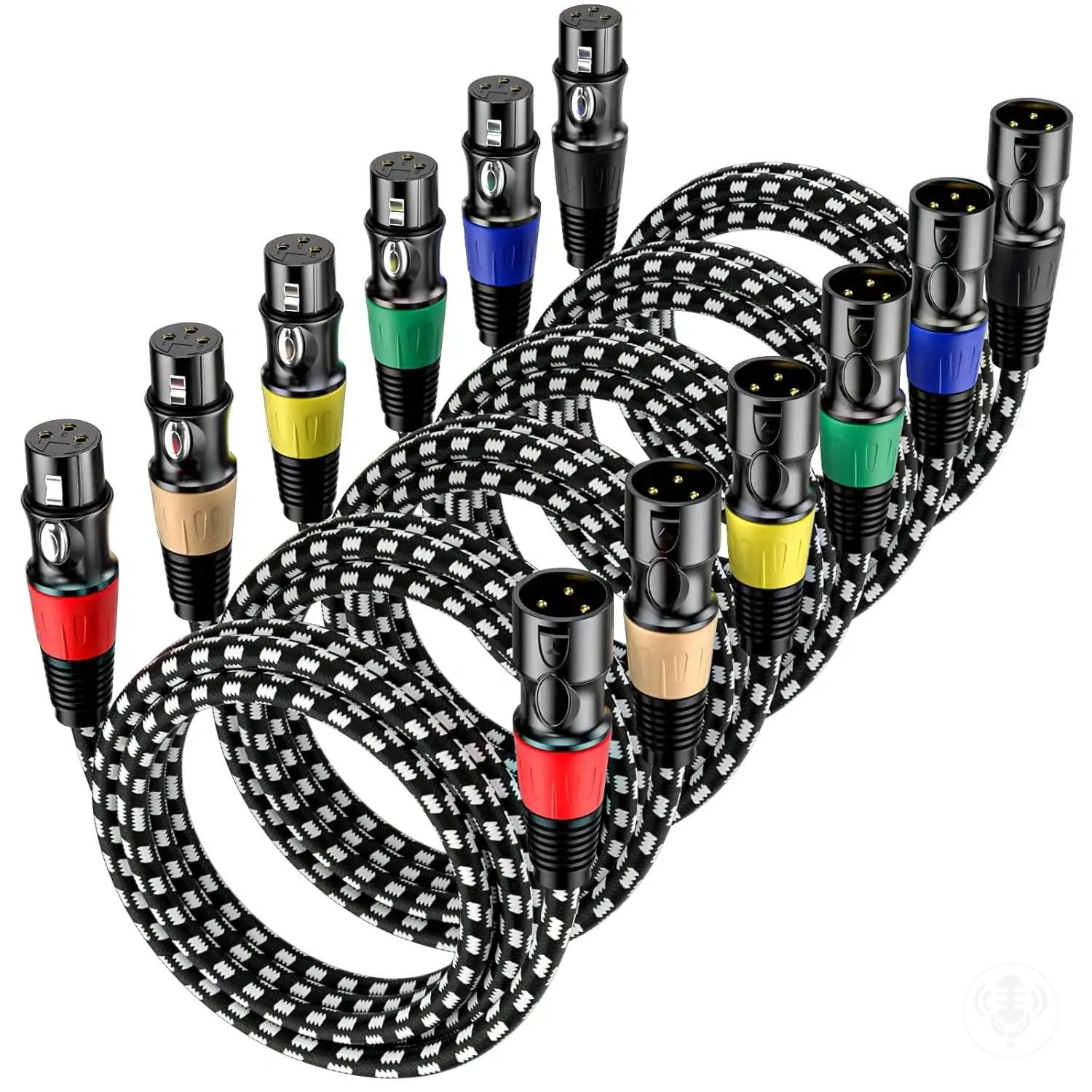
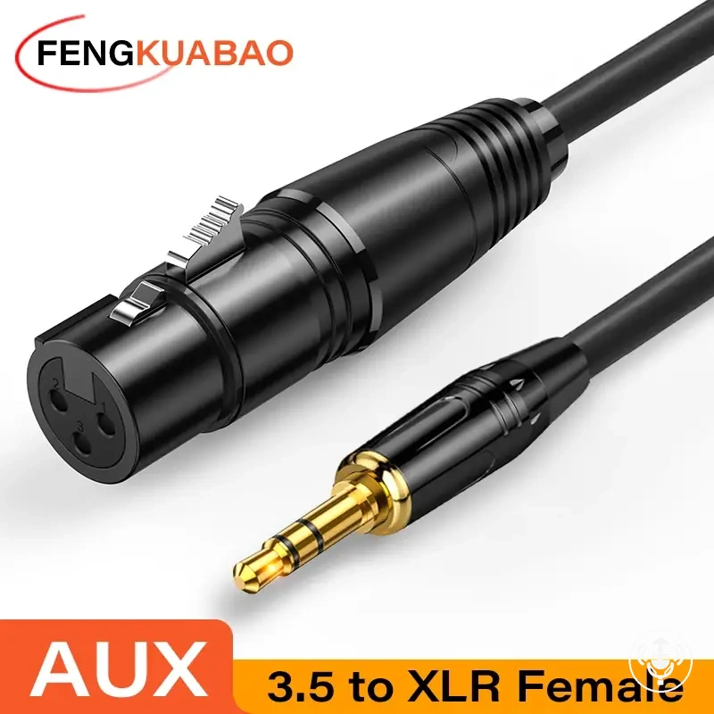
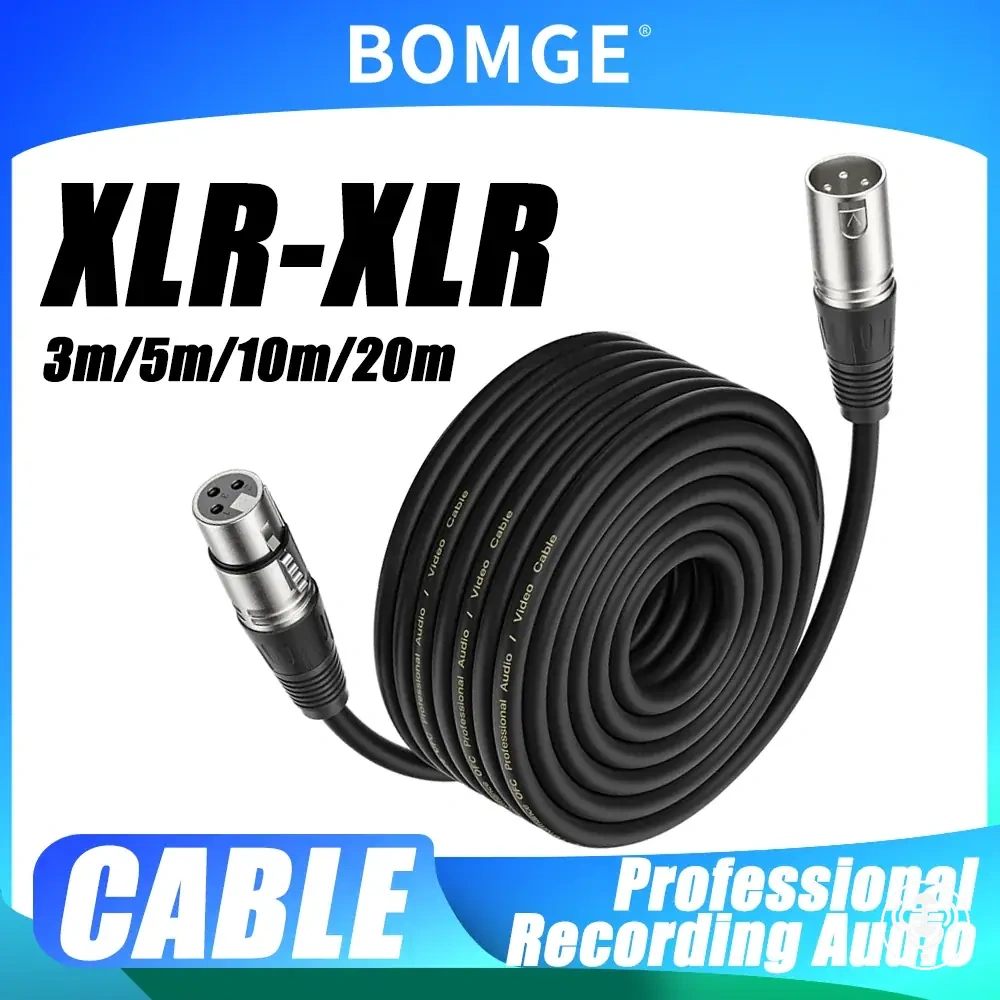
XLR, TRS, and 3.5 mm compatibility depends on connector form, wiring, signal role, channel arrangement, balance configuration, and any required power. A plug can fit mechanically while the electrical or signal path remains incompatible.

XLR is a connector family, TRS describes a tip-ring-sleeve contact arrangement, and 3.5 mm describes connector size. None of those labels alone proves whether the circuit is balanced, stereo, microphone-level, line-level, or capable of supplying microphone power.
| Connector | Common wiring patterns | Balanced or unbalanced implementation | Power behaviour | Typical field-recorder role |
|---|---|---|---|---|
| XLR | Multi-pin microphone or audio wiring; pin function follows the equipment connection | Commonly used for a balanced connection when the source, cable, and recorder input use compatible balanced wiring | Some recorder XLR inputs can supply phantom power when the recorder and connected device support that powering method | Microphone or other compatible audio input |
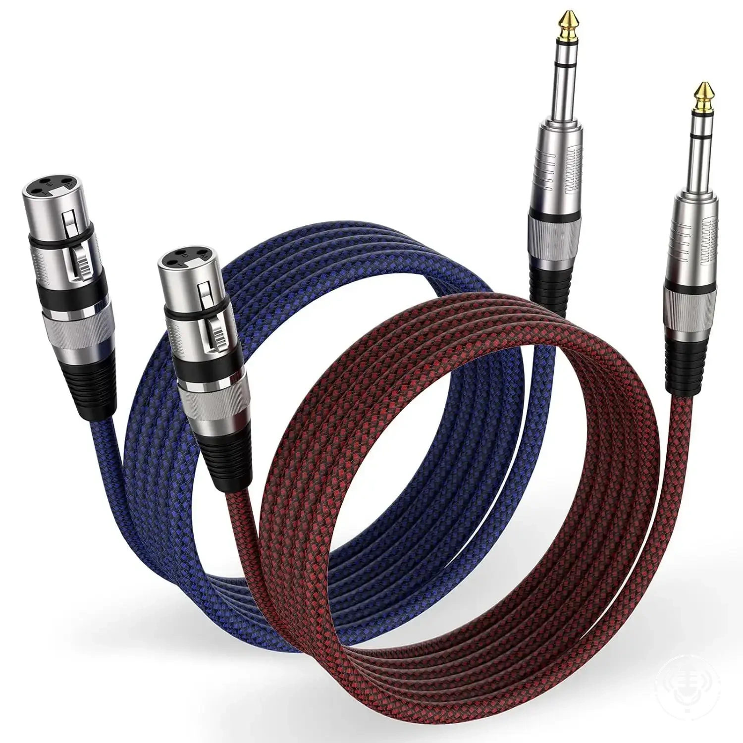
| TRS | Tip, ring, and sleeve contacts; their signal assignment follows the connected equipment | Can carry balanced mono, stereo, or another supported arrangement according to the circuit and wiring | Power behaviour follows the connected equipment and cannot be inferred from the TRS connector alone | Input, output, or monitoring connection according to recorder design |
| 3.5 mm | Contact arrangement follows the stereo, microphone, or other device-specific connection | Can use unbalanced or other device-specific signal arrangements; connector size alone does not establish balance | Some 3.5 mm microphone inputs can provide plug-in power for microphones designed to receive that powering method | Microphone input, stereo input, monitoring output, or another device-specific connection |
Compatibility rule: confirm the contact or pin assignment at both ends, then verify signal level, channel mapping, balanced or unbalanced implementation, and power separately. A cable or adapter establishes only the properties it is designed to carry or convert.
XLR, TRS and 3.5 mm Connectors Use Different Wiring and Balance Configurations
A three-pin XLR connection is commonly wired for balanced mono audio in professional equipment, but the connector format itself does not guarantee that circuit. A three-contact TRS connection can represent balanced mono, unbalanced stereo, or another device-specific assignment.
A 3.5 mm connector describes physical size rather than electrical function; depending on the device, its contacts may carry stereo audio, microphone audio, plug-in power, or another supported arrangement. Balance and channel configuration are properties of the complete circuit and wiring, not the connector appearance alone.
Adapters Can Change Connector Format Without Changing Signal Level or Power Requirements
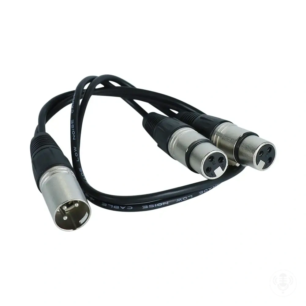
A passive adapter can change the connector format or route wiring between contacts without necessarily converting signal level, balance, channel mapping, or power requirements.
Compatibility therefore depends on identifying which property the adapter changes and which signal or electrical properties it leaves unconverted.
- Mechanical adaptation: changes the physical connector interface while leaving the carried signal and its electrical requirements unconverted.
- Wiring adaptation: routes contacts or conductors between connector formats according to the adapter's wiring arrangement without necessarily changing the underlying signal properties.
- Active signal conversion: uses an active converter designed to convert a specified signal property, such as signal level, rather than merely changing the connector format.
- Power conversion: requires a device specifically designed to convert the available electrical supply or powering method to the form required by the connected equipment.
A passive adapter addresses compatibility only for the connector or wiring property it is designed to adapt, so signal level, channel mapping, balance, and power must still correspond to the recorder and connected device unless the required property is specifically converted.
Active conversion differs because an active converter can be designed to change a defined signal or electrical property rather than only route existing connections.
The required conversion therefore has to match the particular incompatibility in the signal path.
For example, if two devices can be physically joined but their signal levels are incompatible, a passive connector adapter alone does not provide the level conversion needed between them.
Input Count, Channel Count and Track Count Define Recording Capacity
Recording capacity depends on how many simultaneous sources a recorder can physically accept, route through its mixer or signal paths, and record to the required destinations; physical inputs, channel count, and track count can therefore represent different capacity limits.
Routing can further restrict which inputs or channels reach record tracks at the same time, so the largest stated count does not necessarily describe simultaneous recording capacity.
The practical capacity decision is whether the recorder supports the intended source count through the complete input-to-recording path simultaneously.
| Recorder capability | Count or routing attribute | Simultaneous-recording condition | Decision affected |
|---|---|---|---|
| Physical inputs | Number and type of source connections available | Each required simultaneous source needs an appropriate available input unless the recorder supports another suitable input path | How many intended sources can enter the recorder at once |
| Mixer channels | Channel count available for signal handling | Required sources need usable channel paths under the recorder's selected configuration | How many incoming signals can be handled through the required routing |
| Record tracks | Number of recording destinations available | The selected recording mode must support the required tracks concurrently | How many signals can be recorded to the required separate destinations |
| Routing | Supported input-to-channel-to-track assignments | The required physical inputs and channels must be routable to the intended record tracks simultaneously | Whether the available counts support the intended source arrangement |
Physical inputs count the available source connections, channels represent the signal paths available for handling those sources, and record tracks represent the recording destinations available during simultaneous recording.
Together with routing limits and the selected recording mode, these attributes determine whether the recorder can accept, route, and record the required source count at the same time.
The largest advertised channel count or track count should therefore not be treated automatically as the number of usable microphone inputs.
For an illustrative two-source requirement, the recorder needs two suitable source paths that can be accepted, routed, and recorded simultaneously, while a larger multi-source requirement needs enough physical inputs, channels, record tracks, and routing capacity for its greater source count.
The same capacity criteria should guide equipment selection rather than a single maximum channel or track figure.
The practical choice is a recorder whose usable input, channel, track, and routing configuration supports every required simultaneous source in the intended recording mode.
Physical Inputs, Channels and Recorded Tracks Are Different Capacity Measures
A physical input is a hardware connection through which a source enters the recorder, a channel is a signal path used to route or process audio, and a recorded track is a recording destination to which audio is written.
These are separate capacity measures, and their counts do not require a one-to-one relationship.
Manufacturer terminology and the way these measures are labelled can vary between recorder models.
- Physical input: the hardware connection, or input port, that connects a source such as a microphone to the recorder.
- Channel: the signal path through which the recorder can route or process audio according to its supported configuration.
- Recorded track: the recording destination to which a signal is written, including separate destinations used for multitrack recording.
A physical input enables a source to connect to the recorder, a channel enables routing or processing through an available signal path, and a recorded track provides a destination for audio written to the recording.
The number of each can differ according to the recorder's design and configuration, so a hardware connection does not necessarily correspond to exactly one channel or recorded track.
Output Connections Determine Monitoring and Signal-Feed Compatibility
Output compatibility depends on whether the recorder output matches the destination, required signal level, routing purpose, and available monitoring control.
A headphone output is intended for headphone monitoring, while a line output provides a signal feed for a suitable destination input.
Exact output level, control behaviour, shared-output modes, and routing can differ by recorder design and configuration.
Monitoring through headphones and feeding another device are therefore separate compatibility tasks.
- Output type: identify whether the recorder provides a headphone output, line output, or another output mode intended for the required monitoring or signal-feed purpose.
- Destination input: verify that the headphones or downstream device accepts the type of signal supplied by the selected recorder output.
- Level or control behaviour: verify that the recorder's output level and available level control correspond to the receiving device or monitoring requirement; the supported level and control behaviour are model-specific.
- Routing purpose: verify that the required channel or monitoring path can be routed to the selected output in the recorder's intended configuration.
- Connection condition: verify that the connector and wiring provide the required signal path between the recorder output and the receiving device.
A connection problem remains when the recorder output and receiving device physically connect but their signal level, control behaviour, or routing requirements do not correspond.
Check the recorder output type and its level or control behaviour against the destination input, then confirm that routing sends the intended signal through that output.
When those conditions and the physical connection match the receiving-device requirement, the connection can provide the intended monitoring or signal feed.
For personal monitoring, headphones require a suitable headphone output with usable level control, whereas an illustrative feed to another recorder, camera, or mixer requires an output and destination input intended for the required signal feed.
A headphone connection should therefore not be assumed to provide the same output behaviour as a line output merely because both can carry audio.
The compatible connection is the one whose output role, signal level, routing, and control behaviour match the intended destination.
Headphone Outputs and Line Outputs Serve Different Output Roles
A headphone output and a line output can both carry audio, but they are designed for different receiving loads and different signal-delivery roles.
Headphone output
- Intended destination
- Compatible headphones for personal monitoring
- Typical behaviour
- Designed to drive a headphone load and normally provides user level control
- Verify
- Connector, usable level range, headphone load, monitoring routing, and any shared-jack mode
Line output
- Intended destination
- A compatible line-level input on another recorder, camera, mixer, or similar device
- Typical behaviour
- Provides a line feed rather than acting as a headphone amplifier
- Verify
- Nominal output level, destination input requirement, connector wiring, routing, and output control behaviour
If a recorder uses a shared headphone/line jack, the selected mode can change level and output behaviour. Check the recorder's setting and the destination requirement rather than assuming the jack behaves identically in both modes.