
RF, Hum and Electrical Interference in Field Recording Equipment
RF, hum and electrical interference are best diagnosed by changing one condition at a time and looking for a repeatable change in the noise. A response to a nearby transmitter points toward RF pickup, a safe power or ground-path change points toward mains or ground-related interference, and a cable or connector substitution points toward the signal path. Treat sound character as a clue rather than proof, then keep only a cause-specific correction that remains effective when the original trigger is recreated.
Interference diagnostic path
Use the sound only to narrow the candidates. The stronger clue is the controlled change that alters the same symptom repeatably; that response determines the next check and the type of correction to verify.
Interpretation
Choose a pattern and the controlled change that most reliably affects it.
- Why
- Sound character alone is not enough to identify the source.
- Next check
- Change one variable, restore the original condition, and look for the same result again.
- Correction after confirmation
- Apply only a correction that matches the confirmed path, then retest under the original interference condition.
RF energy can become audible when it couples into a susceptible microphone, cable or recorder input and interacts with non-linear electronics; mains, grounding and power paths can create different hum, buzz or whine mechanisms. DPA Microphones and Sound Devices document these mechanisms, but similar audible symptoms can still have different origins.
Table of Contents
Interference Symptoms and Their Likely Causes
Hum, buzz, static, whine, radio breakthrough and intermittent noise are diagnostic clues, not proof of a specific cause.
In a field recording chain, what the sound suggests must be separated from what a controlled confirming check establishes.
The table narrows each symptom family to plausible mechanisms and useful next checks without treating sound character alone as a diagnosis.

| Symptom | Likely mechanism | Confirming clue | Next check |
|---|---|---|---|
| Hum | Mains-related coupling or a ground loop is plausible when the noise changes with the grounding or power path. | The hum changes repeatably after a controlled change to the power source or ground path. | Change one power or grounding condition at a time while keeping the rest of the signal chain unchanged. |
| Buzz or static | Electrical interference or a cable or connector fault is plausible when the artifact follows a particular connection or nearby electrical device. | The buzz or static changes repeatably when one suspect cable, connector or electrical device is changed or isolated. | Change or isolate one suspect connection or electrical device at a time. |
| Radio breakthrough or intermittent RF-like noise | RF pickup is plausible when a nearby transmitter or RF-emitting device couples energy through susceptible shielding, cabling or the recorder input. | The artifact appears, disappears or changes repeatably with the nearby device's operating state or position. | Change the suspect device's operating state or position relative to the recording chain and listen for a repeatable change. |
| Whine or power-related noise | Power-supply noise is plausible when the artifact follows a particular external power source or powered configuration. | The whine or electrical noise changes repeatably when the relevant power arrangement changes. | Compare suitable power configurations while keeping the microphone, cable and recorder input configuration unchanged. |
The strongest symptom-to-cause pattern is one that follows a repeatable controlled change, not the sound alone. The FCC identifies transmitters and electrical equipment as potential interference sources and describes isolating electrical devices individually as a practical way to narrow a source.
RF pickup becomes more plausible when radio breakthrough or intermittent noise tracks a nearby transmitter; hum, buzz or whine becomes more informative when a grounding, cable, connector or power-source change alters it. If none of those controlled checks changes the symptom repeatably, broaden the diagnosis to microphone, recorder-input, gain or other recording faults rather than forcing an interference explanation.
RF Pickup and Radio-Frequency Noise
RF pickup can occur when transmitted energy from a nearby wireless source couples into a susceptible microphone, microphone cable or recorder input and becomes an audible interference artifact.
Sound Devices notes that RF entering microphone electronics can be converted into an audio-band signal, with possible artifacts including hissy or swishing noise, radio breakthrough, beeping or buzz.
The sound alone does not establish radio-frequency interference because the symptom can change with transmitter proximity, microphone cable shielding, recorder input susceptibility and equipment orientation.
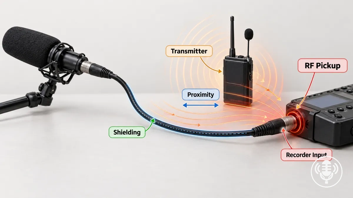
Controlled RF confirmation
- Change one RF condition.Move, reorient or disable one suspected transmitter or RF-emitting device while the rest of the recording chain stays unchanged.
- Look for repeatability.If the same artifact follows that device state, distance or orientation repeatedly, RF involvement becomes more plausible.
- Recreate the original exposure.Return to the original condition before choosing a correction; if the pattern returns, inspect the susceptible cable, microphone electronics or recorder input path.
Ground-Loop Hum and Mains-Frequency Buzz
A ground loop can occur when interconnected powered devices have more than one ground path, allowing unwanted current associated with the power system to enter an audio connection and contribute to hum or buzz.
The diagram shows how separate power paths plus an audio interconnection can form a loop while protective earth remains intact.
Hum can be consistent with a ground loop, but audible hum alone does not confirm one. On Australian mains, a 50 Hz fundamental and its harmonics can be a useful frequency clue; confirmation still depends on a safe power or interconnection change that alters the hum repeatably.
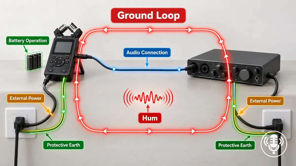
Test a suspected ground loop by changing one supported power or interconnection condition at a time, then restoring the original configuration. A repeatable hum change narrows the suspected path; it does not by itself prove the complete electrical route.
- Compare battery operation with approved external power where the equipment supports both; a repeatable change in hum makes the external-power arrangement a relevant clue.
- Disconnect one nonessential audio connection while leaving required power connections intact; a repeatable change indicates that the interconnection is involved in the suspected ground path.
- Compare one powered device with the configuration containing multiple powered devices; hum that appears or becomes more pronounced with the additional interconnection strengthens the multiple-ground-path hypothesis.
- Return to the original supported configuration and retest the hum; recurrence under the same conditions strengthens the association with that power and connection arrangement.
Cable and Power-Related Electrical Noise
Cable-path and power-path conditions provide different routes for electrical interference to reach a field recorder. On the audio path, signal balance, shield integrity, connector condition and cable routing affect susceptibility; on the power path, external or USB power can conduct switching-related noise into the recording chain.
The illustration separates the microphone-to-recorder audio path from the external power path. The same buzz, hum or whine can therefore change for different reasons, so the useful test is a controlled substitution that alters only one path.
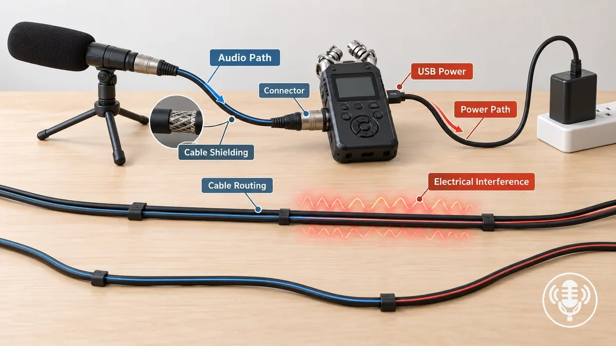
To separate these contributors, make a controlled substitution and check whether the electrical interference changes repeatably.
Audio / cable path
- Substitute a known-working compatible shielded cable when the cable is suspect.
- Check whether normal connector or cable movement reproduces intermittent noise.
- Where applicable, compare a correctly balanced path with an unbalanced path.
- Reroute the cable away from the suspected electrical source and repeat the original exposure.
Power path
- Where supported, compare battery operation with the relevant approved external-power configuration.
- Compare the same audio chain with and without the relevant supported USB or switching-power connection.
- A repeatable change in whine, buzz or hum makes the tested power arrangement more relevant, but does not identify the exact internal mechanism by itself.
Distinguishing Electrical Interference From Recorder Self-Noise and Acoustic Hum
Electrical interference, recorder self-noise and acoustic hum can sound similar, but their source location differs: electrical interference enters through a signal or power path, recorder self-noise originates inside the recording electronics, and acoustic hum exists in the sound field before it reaches the microphone.
A controlled cable change, power change, recorder-input comparison or microphone movement is therefore a stronger discriminator than sound character or spectral appearance alone.
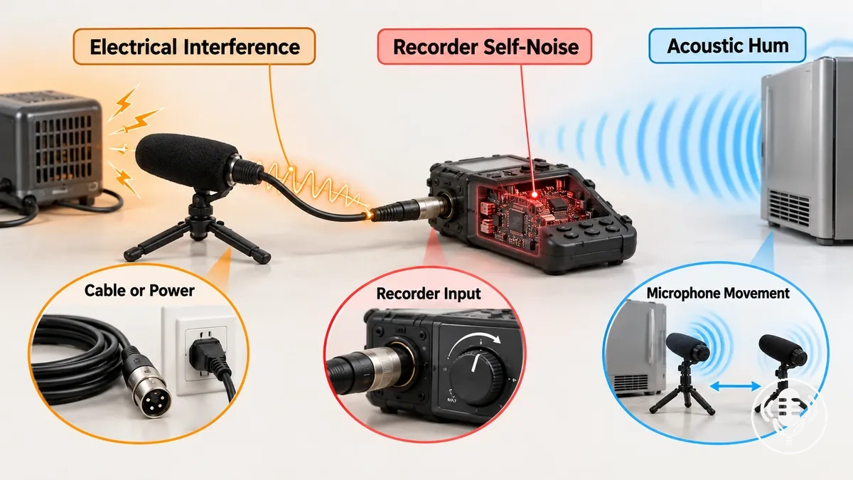
Use source location together with one repeatable response: cable or power changes narrow electrical interference, stable external conditions with recorder-input or gain changes narrow recorder-origin noise, and microphone movement relative to a physical sound source narrows acoustic hum.
| Noise type | Source location | What changes it | Confirming check |
|---|---|---|---|
| Electrical interference | Electrical or signal path leading into the recorder | A relevant cable change or power change may alter the noise when that path is involved. | Change one suspected cable or power condition and check whether the electrical interference responds repeatably. |
| Recorder self-noise | Within the recorder input or other recording electronics | The noise can change with supported input mode or gain because the source is inside the recorder electronics; a gain change alone is not proof. | Hold external acoustic, cable and power conditions stable and compare supported recorder input or gain conditions; repeatability narrows the source to the recorder path. |
| Acoustic hum | Physical sound field around the microphone | Microphone movement relative to the physical sound source may alter the captured hum. | Move or reorient the microphone relative to the suspected physical sound source and check for a repeatable change. |
For example, an electrical appliance can produce physically audible hum that a microphone captures even when the recorder electronics are functioning normally. If microphone movement changes that hum while cable and power conditions stay stable, acoustic origin becomes more plausible.
This source-origin test prevents environmental sound from being mistaken for an electronics fault while keeping recorder noise performance as a separate diagnostic question.
Isolating the Interference Source Along the Recording Chain
Isolate the interference source by changing one variable at a time, keeping every test reversible and safe, and comparing each result with the original condition.
- Set a baseline.Reproduce the symptom and keep recorder settings, environment and unrelated connections stable.
- Change one candidate.Test one microphone, cable, connector, recorder input, power condition or nearby source at a time.
- Reverse and repeat.Restore the original condition, then repeat the changed condition. A result that follows the same variable repeatedly is stronger evidence.
- Move to the next segment only when needed.If there is no repeatable change, keep that candidate lower on the list and continue along the recording chain.
Stop broad testing once one segment reliably reproduces or removes the symptom, then use the relevant detailed check below before choosing a correction.
Test Microphones, Cables and Connectors
Use a known-good compatible substitution for the microphone or cable, or reseat one connector normally, while keeping recorder settings and environmental conditions stable. The useful result is whether the same symptom follows the tested component across repeated comparisons.
- Microphone: Substitute a known-good compatible microphone while retaining the same cable and connector conditions. If the symptom follows the original microphone across repeated comparisons, the microphone becomes a more likely source; if it does not, that possibility becomes less likely.
- Cable: Substitute a known-good compatible cable while retaining the same microphone and recorder connection. Monitor the original symptom during the substitution and normal cable movement; intermittent noise that repeatedly follows one cable makes a cable-related fault more likely, while no repeatable change makes it less likely.
- Connector: Reseat the connector normally while leaving the microphone, cable and recorder settings unchanged. If the symptom follows connector seating across repeated tests, the connector or connection becomes a more likely source; if reseating produces no repeatable change, that explanation becomes less likely.
A repeatable component-linked change increases confidence in that microphone, cable or connector as the relevant source segment; a one-off improvement does not establish the fault.
Test Power and Ground Paths
Compare only safe, manufacturer-supported power conditions while the microphone, cable, recorder settings and environment remain unchanged. Battery operation versus approved external power is a narrowing comparison: a repeatable change makes the power or ground path more plausible, but does not by itself identify the exact device or connection responsible.
- Battery operation: Where the recorder supports battery operation, compare it with the current approved external power configuration while leaving the audio path unchanged. If the hum or interference becomes quieter or disappears repeatably on battery power, involvement of the external power or interconnected ground path becomes more likely; no repeatable change makes that relationship less likely.
- Approved external power: Return to the approved external power configuration without changing the audio path. If the original interference returns repeatably, the audible result strengthens the diagnostic implication that the power configuration or associated ground path is involved; if it does not return, that relationship becomes less certain.
- Powered device: Remove one nonessential powered device from the audio interconnection while leaving required power and safety connections intact. If the interference changes repeatably only when that powered device is interconnected, its involvement in the tested ground path becomes more likely; no repeatable change makes it less likely.
- Simplified interconnection: Where the equipment permits it, compare a simplified interconnection with the original supported arrangement. If the interference decreases repeatably with the simpler arrangement, an inter-device power or ground-path relationship becomes more likely; no repeatable change weakens that explanation.
If a power-path test changes the symptom, restore the original safe configuration and repeat the changed condition. A repeatable result makes that power or ground-path relationship more likely; quieter battery operation narrows the path but does not prove which powered device or interconnection is responsible.
Check Nearby Electrical and RF Sources
Test one nearby electrical or RF source at a time by changing only its operating state, distance or orientation while the recording chain stays fixed. A repeatable on/off, distance or orientation effect makes that source more likely to contribute without proving the exact coupling path.
- Mobile device or wireless transmitter: Change the operating state of one mobile device or wireless transmitter, or alter its proximity or orientation relative to the recorder and cable. If the interference changes repeatably with that single condition, the RF source becomes more likely to contribute; no repeatable change makes it less likely under the tested condition.
- Computer or camera: Change the operating state or proximity of one nearby computer or camera while the recording chain remains fixed. If the symptom follows that controlled change repeatedly, the device becomes a stronger candidate source; no repeatable change weakens that association.
- Charger or switching supply: Where the test does not alter the recorder's required power configuration, change the operating state or proximity of one nearby charger or switching supply. A repeatable interference change makes that nearby electrical source more likely to contribute, while no repeatable effect weakens the association.
- LED lighting or dimmer: Change the operating state of one LED lighting fixture or dimmer while leaving the recording chain unchanged. If the interference repeatedly follows the on/off test, that electrical source becomes more likely to be involved; no repeatable change makes it a weaker candidate under that condition.
- Another nearby powered device: Test one other suspected powered device by changing only its operating state, proximity or orientation. If the interference changes repeatably with that single variable, the device becomes a stronger candidate; if it does not, the device becomes a weaker candidate under the tested condition.
Retest both the original and changed conditions before treating the device as a leading candidate; no repeatable effect makes that source less likely under the tested condition.
Reducing Interference in Microphone and Recorder Connections
Choose the corrective measure from the diagnosed path rather than changing cables or accessories indiscriminately. Balanced signalling and shielding address signal-path susceptibility, routing addresses exposure, signal-path isolation addresses an identified ground path, and RF suppression addresses confirmed RF coupling.
Each correction needs a verification check under the original interference condition; the table links the diagnosed condition to the expected change and the test that should confirm it.
| Diagnosed condition | Corrective measure | Expected change | Verification check |
|---|---|---|---|
| Susceptible unbalanced or poorly shielded signal path | Use appropriate balanced signaling where the connected equipment supports it, or restore shielding integrity where the cable or connection has been identified as compromised. | Interference associated with that signal path should decrease if its susceptibility was contributing to the problem. | Retest the original interference condition with the corrected signal path while keeping other relevant conditions stable. |
| Diagnosed ground-loop path between interconnected equipment | Use safe signal-path isolation appropriate to the identified ground path while preserving required protective grounding. | Hum associated with that ground path should decrease if the isolated signal path was contributing. | Retest under the original connection and power conditions and confirm that the hum reduction follows the corrective measure. |
| Cable-routing exposure near an interference source | Change cable routing to increase separation from the diagnosed source or reduce unnecessary parallel exposure. | Interference should decrease if the original routing was contributing to coupling. | Compare the original and revised cable routing under the same source operating condition and confirm a repeatable change. |
| RF coupling associated with a nearby transmitter | Apply RF suppression suited to the affected signal path or connection after the coupling has been narrowed to that path. | The RF-related interference should decrease if the suppression addresses the susceptible coupling point. | Retest with the nearby transmitter under the original operating condition and confirm that the interference reduction is repeatable. |
If the correction does not produce the expected repeatable change, reassess the diagnosed cause instead of stacking unrelated fixes.
Prefer the least invasive cause-specific measure that repeatedly reduces the original interference while preserving required signal integrity and safety conditions.
Use Balanced and Shielded Audio Connections
Balanced signalling can reduce common-mode interference when the source impedance balance, cable wiring, connector termination and a compatible differential recorder input form a balanced path together. A shielded cable also depends on intact shield continuity; an XLR connector by itself does not prove that the complete path is balanced or effectively shielded.
Cable routing remains a separate attribute: moving a correctly wired cable away from a diagnosed interference source can reduce exposure even when the electrical topology is unchanged.
Correct only the identified balance, shield, termination or routing condition, then retest under the same interference exposure. A balanced or shielded path reduces susceptibility; it is not automatically immune to interference.
Isolate Ground Loops in the Audio Path
Use signal-path isolation only when repeated testing supports a ground loop involving the audio path between interconnected powered devices. The objective is to interrupt the unwanted signal-path ground current while protective earth remains intact.
If the hum does not follow the suspected ground-path condition, use a correction that matches the diagnosed cause rather than adding isolation because the noise happens to be low-frequency.
- Confirm the suspected loop: Verify that the hum responds repeatably to the previously identified ground-path condition between the powered devices before applying isolation.
- Isolate the audio path safely: Use a signal-path isolation method appropriate to the connection while keeping protective earth intact; if the diagnosed ground loop is contributing, the hum should decrease when the unwanted current path is interrupted.
- Verify the result: Recreate the original hum condition, then compare the hum, signal level and signal integrity with the safely isolated audio path.
Keep the isolation only when the hum reduction is repeatable under the original condition and the change has not introduced unwanted level or signal-path side effects.
Reduce RF Coupling Around Cables and Equipment
Reduce RF coupling only after testing links the interference to a nearby transmitter or a susceptible cable, microphone or recorder input. The corrective aim is to reduce exposure or coupling at that diagnosed path, then check whether the same RF-related symptom decreases.
Effectiveness depends on frequency, transmitter position, cable geometry, shielding or balance, equipment susceptibility and the coupling path, so no single RF mitigation is universal.
- Increase distance: Increase the distance between the diagnosed transmitter and the susceptible cable or equipment where practical, then retest with the transmitter in its original position and operating condition. A repeatable reduction in RF pickup supports reduced exposure as an effective mitigation for that arrangement.
- Change cable routing or orientation: Reposition the susceptible cable or change its orientation relative to the transmitter while keeping other conditions stable, then recreate the original transmitter condition. A repeatable reduction supports the revised cable routing or orientation as relevant to reducing RF coupling.
- Shorten the exposed run: Where practical, shorten the portion of cable exposed near the diagnosed RF source without changing unrelated connections, then retest under the original exposure. A repeatable reduction indicates that the shorter exposed run reduces susceptibility in that arrangement.
- Improve shielding or balance: Where the connection supports it, correct compromised shielding or restore the intended balance of the audio path, then retest with the same transmitter exposure. A repeatable reduction indicates that shielding or balance was relevant to the diagnosed RF coupling path.
- Apply appropriate RF suppression: If testing has narrowed RF coupling to a particular susceptible point, use RF suppression appropriate to that connection and equipment, then repeat the original exposure. Suppression effectiveness can differ with frequency, cable type, device design and coupling path, so verification must establish whether the selected mitigation reduces the diagnosed symptom.
If a mitigation reduces the interference, reverse and repeat the comparison and recreate the original transmitter condition. Keep the change only when the reduction remains associated with the same distance, routing, orientation, shielding, balance or RF-suppression condition.
Confirming the Interference Is Removed Before Recording
Recreate the original interference conditions before relying on the correction. Use monitoring and a short test recording, then verify the conditions that previously exposed the problem.
- Monitoring: Recreate the original interference conditions and monitor the corrected field recording chain. The expected result is that the original unwanted noise remains absent; if the observed result is clean and repeatable, pass this check, but if the noise recurs, return to further diagnosis.
- Test recording: Make a short test recording with the relevant operating conditions unchanged. The expected result is a recording without the original interference; compare the observed result with the monitored signal and pass when the clean result is repeatable, otherwise continue diagnosis.
- Cable movement: Repeat the cable movement that previously exposed or changed the symptom, where applicable. The expected result is no recurrence during that movement; if the observed result remains clean across repeated checks, pass, but recurrence points back to the cable or connection path for further diagnosis.
- Power-state change: Recreate the relevant power-state change that previously affected the interference while retaining the same supported operating conditions. The expected result is that the correction remains effective through that change; pass when the observed result is repeatably clean, or return to diagnosis if the interference follows the power condition again.
- Suspected source: Restore the previously suspected RF or electrical source to the position, orientation or operating state associated with the original symptom. The expected result is no recurrence of the interference; a repeatable clean result supports the correction, while recurrence requires further diagnosis of that source or coupling path.
Repeated clean results support the correction under the tested conditions; they do not prove that recurrence is impossible in every environment. If the symptom returns, run another diagnostic pass before normal recording, then continue with the broader equipment setup checks.